When it comes to sourcing the right hydraulic adapter, the key to efficiency lies in speaking a common technical language. That’s why understanding the standard code system—such as the one used by Eaton and Winner—is crucial. At AKJia Hydraulic, we adopt the same hydraulic adapter coding rule to make it easier for our customers to identify and order the exact adapter they need.
Why the Adapter Code Matters
Hydraulic adapters come in a wide variety of thread types, sizes, shapes, and connection ends. Without a clear system to describe these combinations, communication between buyers and manufacturers can become slow and error-prone.
Eaton, a global leader in hydraulic solutions, developed a widely recognized part number coding system. After acquiring Winner Hydraulics in Ningbo, Eaton continued using this standard—now well-accepted throughout the industry.
We follow the same adapter code rule on our website. If you’re already familiar with Eaton or Winner part numbers, you can quickly find the exact adapter you’re looking for.
Understanding the Hydraulic Adapter Code
A typical hydraulic adapter code may look like this:
1BG9-08-06SS
Let’s break it down:
- 1BG9 – Adapter type, Shape and Thread Info
- 08 – Thread Size on the first end
- 06 – Thread Size on the second end
- SS – The Material, if blank, 1BG9-08-06, it is a carbon steel, and SS, is stainless steel, and BR is Brass.
Hydraulic adapters can be categorized into straight adapters, 45° elbow adapters, 90° elbow adapters, tee adapters, and cross adapters. The first part of the number is used to distinguish these classifications.
Straight Adapter Code Rule
Le item code of a straight adapter consists of four parts. The first part identifies the adapter model, where different numbers and letters represent specific thread types. The second et third parts indicate the thread sizes of each end, respectively. The fourth part provides additional details such as the material, sealing ring type, or other special features.
45˚ Elbow Adapter Code Rule
The item code of a 45˚ elbow adapter is easy to understand based on the straight adapter code. Just add a number of 4 at the end of the first part of the code. For example, 1BG-08-06 is a straight adapter, and the 1BG4-08-06 is the 45˚ Elbow Adapter.
90˚ Elbow Adapter Code Rule
Same to 45˚ Elbow Adpater, the 90˚ Elbow Adapter also just add a number of 9 at the end of the first part of the code,based on the straight adapter.
Tee Adapter Code Rule
Tee adapter code rule has addtional middle thread size, the first part is also the information of the adapter model. second to fourth part for the thread left, thread middle and thread right, then finally part for the addtional information like Material, O ring etc.
Cross Adapter Code Rule
The Cross adapters usually the 4 ends are same, that the code would be more simple. The first part of the code rule would be the adapter series with the information of the thread type, and the second part for the thread size. And the following addtional information like materials and O-ring etc. and if for some special applications, they request the different thread size, it would be following the left, up, right, down.
2 ends Adapters name Rule
Le straight adapters, 45˚ Elbow Adapters et 90˚ Elbow Adapters are all have 2 ends, the ends can be male thread, female thread(fixed),Swivel Female Thread etc. And the thread types can be BSP Thread with 60° Cone Seat, BSPP Female Flat Face with O-Ring Seal,Metric 24° Light Type and so many options. In order to easy to decribe the adapter, Eaton given a easy rule to describe the information.
| The first Number ( for the treads types) | Second or Third letter( same thread only one letter, differnt 2 letters) |
|---|---|
| 1 – male thread to male thread | A – BSP Thread with Spherical (Ball) Seat |
| 2 – male thread to Swivel Female Thread | B – BSP Thread with 60° Cone Seat |
| 3 – Swivel Female Thread to Swivel Female Thread | C – Metric Thread, 24° Cone, Light Series(L) |
| 4 – Male Thread Plug (one end male thread and another end close off) | D – Metric Thread, 24° Cone, Heavy Series(S) |
| 5 – Male Thread to Fixed Female Thread (also called Threaded Reducing Bushing) | E – Metric Thread with Flat Face and O-Ring Seal |
| 6 – Bulkhead | F – SAE ORFS (O-Ring Face Seal) |
| 7 – Fixed Female Thread to Fixed Female Thread | G – BSPP Flat Face with O-Ring |
| 8 – Lock Nut (usually work with Bulkhead adpater) | H – Metric Hex Plug with O-Ring on End Face |
| 9 – Female Thread Plug ( one end female thread and another end close off) | J – JIC 37-Degree Flare |
| K – Metric Male Thread with 60° External Cone (Komatsu Style) | |
| L – Metric Thread with Bonded Seal (washer made of metal + rubber) | |
| M – Metric Thread with 60° Cone Seat | |
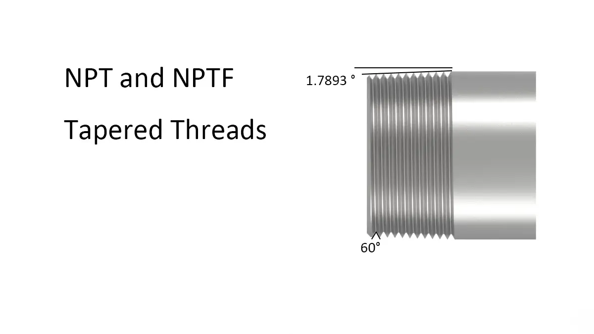
| N – American Tapered Pipe Thread (NPTF) | |
| O – SAE ORB (O-Ring Boss) Thread | |
| P – SAE 45° Flare (90° Included Angle) | |
| Q – Metric 37° Flare (74° Included Angle) | |
| S – Japanese BSPP Male Thread with 60° External Cone | |
| T – British Standard Taper Pipe Thread (BSPT) | |
| U – NPSM | |
| W – Welded Pipe | |
| Y – Mining Connector (SAE Standard) | |
| Z – BSPP Flat Face with Combination Washer Seal (a metal washer with a rubber insert used for sealing) |
The table above helps quickly identify the meaning behind different hydraulic transition joint codes. For example, 1 indicates a fitting with external threads on both ends. When a code contains only one letter—like C—it means that both ends have the same type of thread.
In this case, the letter C represents a metric 24° light thread. This is often followed by a number, which specifies the thread size. For example:
1C-12 means a transition joint with two external metric 24° light threads, and the size 12 refers to M12x1.5 thread.
And if 1C-12-14, it will be one end thread is M12x1.5 and another is M14x1.5.
And if 1CG-12-02, C is Metric Thread, 24° Cone, and G is BSPP Flat Face with O-Ring, then one end is M12x1.5 and another thread is BSPP 1/8″-28. ( The number for the thread size see another table)
3 ends (TEE) Adapter Name Rule
Since numbers are already used to identify two-port adapters, Eaton uses letters to distinguish three-port adapters.
- Le first letter in the code represents the port type combination specific to the three-port adapter.
- Le subsequent letters follow the same convention used for two-port adapters to indicate the thread types and specifications at each port.
| The first letter ( for the treads types) | Following letter (if threa some only 1 letter, or 3 letters) |
|---|---|
| A – Male Thread / Male Thread / Male Thread | A – BSP Thread with Spherical (Ball) Seat |
| B – Male Thread / Swivel Female Thread / Male Thread | B – BSP Thread with 60° Cone Seat |
| C – Male Thread / Male Thread / Swivel Female Thread | C – Metric Thread, 24° Cone, Light Series(L) |
| D – Swivel Female Thread / Swivel Female Thread / Swivel Female Thread | D – Metric Thread, 24° Cone, Heavy Series(S) |
| E – Swivel Female Thread / Male Thread / Swivel Female Thread | E – Metric Thread with Flat Face and O-Ring Seal |
| F – Swivel Female Thread / Swivel Female Thread / Male Thread | F – SAE ORFS (O-Ring Face Seal) |
| G – Fixed Female Thread / Fixed Female Thread / Fixed Female Thread | G – BSPP Flat Face with O-Ring |
| H – Fixed Female Thread / Fixed Female Thread / Male Thread | H – Metric Hex Plug with O-Ring on End Face |
| J – Fixed Female Thread / Male Thread / Fixed Female Thread | J – JIC 37-Degree Flare |
| K – Male Thread / Fixed Female Thread / Male Thread | K – Metric Male Thread with 60° External Cone (Komatsu Style) |
| L – Male Thread / Male Thread / Fixed Female Thread | L – Metric Thread with Bonded Seal (washer made of metal + rubber) |
| M – Swivel Female Thread / Fixed Female Thread / Swivel Female Thread | M – Metric Thread with 60° Cone Seat |
| N – Male Thread / Fixed Female Thread / Swivel Female Thread | N – American Tapered Pipe Thread (NPTF) |
| P – Fixed Female Thread / Male Thread / Swivel Female Thread | O – SAE ORB (O-Ring Boss) Thread |
| Q – Fixed Female Thread / Swivel Female Thread / Male Thread | P – SAE 45° Flare (90° Included Angle) |
| Q – Metric 37° Flare (74° Included Angle) | |
| S – Japanese BSPP Male Thread with 60° External Cone | |
| T – British Standard Taper Pipe Thread (BSPT) | |
| U – NPSM | |
| W – Welded Pipe | |
| Y – Mining Connector (SAE Standard) | |
| Z – BSPP Flat Face with Combination Washer Seal (a metal washer with a rubber insert used for sealing) |
For example, ACCH-12-12-10OG
1. Prefix: Connection Gender (A)
The first letter defines the gender of the three connection ports.
- A: Stands for an all-male tee, meaning all three ports have external threads.
2. Body: Port Connection Types (CCH)
The next series of letters describes the type of connection for each port on the tee, typically in the order of (Run 1 – Run 2 – Branch).
- C: Represents a Metric 24° Light Series cone connection (DIN 2353/ISO 8434-1).
- H: Represents a Metric O-Ring Boss connection, which uses a hexagonal end face with an O-Ring for sealing (ISO 6149).
In our example, ACCH:
- Port 1 (Run):
C– Metric 24° Light Series - Port 2 (Run):
C– Metric 24° Light Series - Port 3 (Branch):
H– Metric O-Ring Boss
3. Sizing: Thread Dimensions (12-12-10)
The numbers correspond directly to the thread sizes of the ports listed in the previous step.
- 12: Corresponds to an M12x1.5 thread.
- 10: Corresponds to an M10x1.0 thread.
For ACCH-12-12-10OG:
- Port 1 Thread: M12
- Port 2 Thread: M12
- Port 3 Thread: M10
4. Suffix: Application Type (OG)
The suffix indicates the intended use or style of the fitting.
- OG: Specifies the fitting is for a standard inline or “butt joint” connection.
- G: This alternative suffix would indicate a Gauge Joint, specifically designed with a port for connecting pressure gauges or diagnostic equipment.
Cross Adapter Name Rule
Because usually cross adapters the 4 ends are same. X means 4 male threads, Y means 4 Swivel Female Threads and Z means 4 fixed Female Threads. for example XB-08, 4 BSP male Threads with 60° Cone Seat.
Thread Size Code
The table for the size code for US Standard Threads and British Standard Threads. The Size code x 1/16 is the thread size
| Size Code | 02 | 04 | 05 | 06 | 08 | 10 | 12 | 16 | 20 | 24 | 32 |
|---|---|---|---|---|---|---|---|---|---|---|---|
| BSP Thread | G1/8“x28 | G1/4“x19 | – | G3/8″x19 | G1/2″x14 | G5/8″x14 | G3/4“x14 | G1″x11 | G1.1/4″x11 | G1.1/2″x11 | G2″x11 |
| Filet BSPT | R1/8″x28 | R1/4“x19 | – | R3/8″x19 | R1/2″x14 | – | R3/4“x14 | R1″x11 | R1.1/4″x11 | R1.1/2″x11 | R2″x11 |
| Filetage NPT | Z1/8″x27 | Z1/4″x18 | – | Z3/8″x18 | Z1/2″x14 | – | Z3/4“x14 | Z1″x11.5 | Z1.1/4″x11 .5 | Z1.1/2“x11 .5 | Z2″ x11 .5 |
| JIC Thread | – | 7/16″x20 | 1/2″x20 | 9/16″x18 | 3/4″x16 | 7/8″x14 | 1.1/16″x12 | 1.5/16″x12 | 1.5/8″x12 | 1.7/8“x12 | 2.1/2″ x12 |
| ORFS Thread | – | 9/16″x18 | – | 11/16″x1 6 | 13 /16″x16 | 1″x14 | 1.3/16″x12 | 1.7/16″x12 | 1.11/16″x12 | 2″x12 | – |
| SAE Thread | – | – | – | 5/8″x18 | – | 1.1/16″x14 | – | – | – | – | |
| Flange size | – | – | – | – | 1/2″ | 5/8″ | 3/4″ | 1″ | 1.1/4″ | 1.1/2″ | 2″ |
Metric Thread the size code is the diameter of the thread, like M12x1.5, the code is 12.
Addtional Code
The default code have described the the adpater types, threads, and thread size, and the addtional code are usually give some more information like the material, the O-ring, the Nut etc.
The Adapter Material
| Matériau | Acier au carbone | Laiton | Acier inoxydable |
|---|---|---|---|
| Code | – | BR | SS |
Le 1BG straight-through adapter series features a G1/2”X14 thread on the left end and a G3/4”X14 thread on the right end. When made of acier au carbone, the part number is 1BG-08-12. If made of acier inoxydable, the part number becomes 1BG-08-12SS.
Other Codes
- Adding “OR” after the original item code indicates that an O-Ring is added on the 60°, 74°, or 90° external cone surface.
- Example: 1J-06-04OR means the -04 end (second end) has an O-Ring on the cone surface.
- 1J-06-04/2OR means both ends (-06 and -04) have O-Rings.
2. Fixed female thread / Swivel female thread (crimped nut) is indicated with a starting digit “7” and an “S” at the end (Note: “S” stands for Swivel).
- Example: 7B-08S, 7NU-08S.
3. Male thread / Swivel female thread (loose nut) is indicated with a starting digit “5” and an “S” at the end.
- Example: 5J-08-12S.
4. Short W-end welded tubes are marked with an “S” at the end (Note: “S” stands for Short).
- Example: 3BW-08-20S
5. For straight tubes used in compression fittings, use “W” followed by “P”.
- Example: 1BW-08-18P indicates the second end is a straight tube for compression fittings, not for welding.
6. If the welded tube size is in inch units, add “IN” at the end.
- Example: 5JW-08IN, 3JW-12S/IN.
7. Hex socket male plug fittings are marked with an “N” in the original code.
- Examples: 4TN-08, 4NN-08, 4BN-08, 4ON-08.
8. Fittings with captive seal are marked with “WD” at the end.
- Example: 1B-08-12WD means the -12 end uses a captive seal.
- 1B-08-12/2WD means both -08 and -12 ends use captive seals.
9. Transition adapters with extended J-end are marked with “L” at the end.
- Example: 1JO-08L.
10. Gauge adapters are marked with “G” at the end.
- Example: 2TB-08G.
11. Cross adapters are marked with “OG” at the end.
- Examples: 1JG9-08-10OG, AJOJ-08OG.
12. T-end fittings that require internal 60° cone machining are marked with “SP” at the end.
- Example: 1BT-08SP.
13. 24° cone seal fittings with O-Ring that use GB standard O-Rings are marked with “GN” at the end.